IMSAI 8080 Replica Build & First Programs
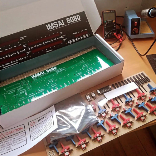
The IMSAI 8080 kit from The High Nibble is pretty neat, and fun to build. It emulates a 1970s IMSAI 8080 microcomputer system with an Intel 8080 CPU running @2MHz. It is capable also of emulating other peripherals such as floppy drives. It behaves as a functional replica of a system, and is compatible with original programs and operating systems, like the once-popular CP/M. Here I’ll look at a barebones configuration, and how to use/interpret the front panel.
 |
 |
The computer
Released in 1975, the IMSAI 8080 was a clone of the Altair 8800. The way these machines work is not too dissimilar to modern computers. Programs are loaded into memory, and the CPU executes programs from there. On modern machines, usually an operating system (Windows, Mac etc) will load a program from disk into memory prior to execution.
In a barebones configuration, this machine has no operating system. So how then can an inital program be loaded? The answer is the front panel. These switches and LEDs allow a human user to inspect and manipulate memory by hand. By halting the CPU and storing byte-by-byte values that correspond to CPU instructions, a program can slowly be loaded.
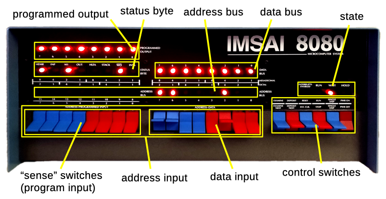
Other indicators show for example the state of the CPU and busses both when the CPU is running and at rest. This page goes into more detail on some of these aspects.
Some Front Panel Programs
The machine code of these following programs is listed in octal instead of hex – this as it is a bit easier to enter and seemed more common in program listing of the time (additionally the encoding of Intel 8080 instructions also lends itself to octal representation)
An Infinite Loop
Assuming the program begins at address 0, an infinite loop can be written as a JUMP back to 0. This in Intel 8080 assembly could be:
000: JMP 0x0000 ; 303 000 000
The program can be input via the front panel:
- holding
RESETresets machine state - switches all down and
EXAMINEsets the current address to0 - switches to octal
303andDEPOSITstores the opcode forJMP - switches all down and
DEPOSIT NEXTstores0at address1: the data display is cleared (data value0) and the address is incremented - this is repeated for the final byte
With the program now in memory, we can SINGLE STEP through it :
- switches to address
0andEXAMINE. This sets the program counter SINGLE STEPexecutes the first part of the instruction:303is fetched from memory.- The
M1LED in the status byte turns off as it is only illuminated on the first byte of the instruction cycle. The address bus is incremented, and the data bus shows0, the low byte of the jump destination.SINGLE STEPagain.. - The address is incremented, and the data display shows
0– the high byte of the jump destination.SINGLE STEPagain.. - The address shows
0and the data303– indicating the CPU has jumped. SINGLE STEPping a few more times repeats this cycle- By toggling
RUN, the CPU executes the program without intervention
Echo
A simple program that continuously polls the “sense” switches and writes to the output display. The sense switches & output can be read/written from/to the A register using the IN/OUT instructions at port address 0xFF hex 377 octal. The output shows the output inverted (LED on when bit=0). Instruction CMA (CoMplement A) can be used to invert the value before writing to the port.
000: IN      0xFF   ; 333 377
002: CMA            ; 057
003: OUT     0xFF   ; 323 377
005: JMP     0x0000 ; 303 000 000
A Simple Adder
This small program takes input again from the sense switches, and provides output on the output display. It takes the two nibbles (4 bits, i.e. the group of red and group of blue switches) as separate numbers, and adds them together.
000: IN     0xFF   ; 333 377
002: MOV    B, A   ; 107       (store a copy in B)
003: RRC           ; 017       (shift A right 4x)
004: RRC           ; 017
005: RRC           ; 017
006: RRC           ; 017
007: ANI    0xF    ; 346 017   (take lower 4 bits)
011: MOV    C, A   ; 117       (tmp store in C)
012: MOV    A, B   ; 170       (get original state)
013: ANI    0xF    ; 346 017   (get lower 4 bits)
015: ADD    C      ; 201       (add C to A)
016: CMA           ; 057
017: OUT    0xFF   ; 323 377
021: JMP    0      ; 303 000 000
Front panel bootloaders
Programming via the front panel can get tedious quickly, and is pretty error prone (the last program took me a few attempts..). The original systems and the replica have serial ports that allow connections to teletypes & terminals. This would allow input from some keyboard and text output. By entering a short bootloader program by hand, this could in turn load a larger program into memory via the serial port (e.g. demonstration video on an Altair). Such programs may be higher level programming environments (such as BASIC) that would make it easier to program the system.
