Electronic Business Card Puzzle
Feeling inspired after seeing some electronic business cards creations, I tried a few years ago to make mini variant of my own. It’s a neat form factor to experiment and demo some ideas. Built around an ATtiny85 microcontroller, this was my first PCB design. The board is a sort-of puzzle, incorporating elements from different interests like (retro)computing, electronics and music.
The Puzzle
Hint: the solution is one word: some foodstuff.
The board has a minimal number of components. At first sight, pushing the button doesn’t seem to reveal much. An LED stays on for roughly 15s before turning off again. But if you hold the board close to an AM/SW radio, you notice it gives off some distinctive radio-frequency interference:
Analysing the audio
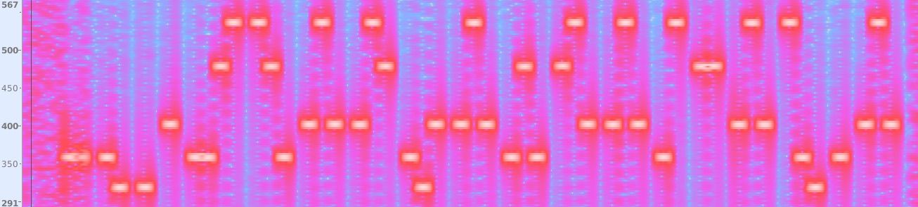
A recording of the full audio pattern is below. A spectrogram of the recording from Audacity could be used to analyse the sound further:
(Note: from this point on, physical board not required.. spoilers ahead)
It reveals a series of 5 different pitches in sequence, sometimes with small pauses inbetween. With the mostly regular rhythm it sounds almost musical: it might be helpful to transcribe at this point. The musical gamut consists of 5 pitches – from lowest to highest – E, F#, G#, B, C#. This is a major pentatonic scale, starting on E.

This fact could be helpful as a means of decoding the pitches into numeric values. There is additionally a rest dividing the pitches into groups with the group size varying between 1-4 notes. This could be a means of delimiting multiple values.
Base-5 Arithmetic
In our normal number system, we have 10 different digits for each place value – this is base-10. A property of positional notation is the number 307 in base 10 (\(307_{10}\)) can be written:
\[307_{10} = 3 \times 10 ^2 + 0 \times 10^1 + 7 \times 10^0\]Binary and hexadecimal used in computing correspond to bases 2 and 16 respectively. \(307_{10}\) can also be written in base 5 as:
\[2202_{5} = 2 \times 5^3 + 2 \times 5^2 + 0 \times 5^1 + 2 \times 5^0\] \[2202_{5} = 250 + 50 + 5 + 2\] \[2202_{5} = 307_{10}\]Counting from 0, we can label the pitches in the above tune by their position in a lo-hi order / or position in the pentatonic scale, utilising the rests to separate groups of digits. With this we can begin to decode the mystery tune:

Decoding the mystery tune
Following this through with the rest of the tone groups gives the sequence:
6, 5, 0, 2, 169, 116, 72, 73, 27, 72, 41, 97, 72, 9, 18, 72, 105, 1, 72
The first four digits provide a clue – the 6502 CPU is a CPU once popular in early computers of the 1970s. Modern variants are still in production today. It powered the first Apple computer – the Apple I (see also breadboard replica from a previous project), and a 6502 variant was the brains in the Nintendo Entertainment System.
The rest of the numbers are conveniently in the range 0..255 – the range of an 8-bit byte. Perhaps the following numbers could be a program for the 6502 in machine code form?
Disassembling the Program
For this it is first easiest to convert the rest of the numbers to hexadecimal. Instructions on the 6502 consist of a single byte, followed by 0 or more “argument” bytes. We can use an opcode map to find the correct machine instruction for a byte, and see how many of the immediate following bytes belong to this instruction. The opcode map can also be found in the manufacturer’s current datasheet for the W65C02S.
| # | Base 10 Hex |
Instruction | Description |
|---|---|---|---|
| 1 | 169 116a9 74 |
LDA #$74 |
Load accumulator with constant value 0x74 |
| 2 | 7248 |
PHA |
Push contents of accumulator to stack |
| 3 | 73 2749 1b |
EOR #$1b |
Bitwise XOR accumulator with constant value 0x1b |
| 4 | 7248 |
PHA |
Push contents of accumulator to stack |
| 5 | 41 9729 61 |
AND #$61 |
Bitwise AND accumulator with constant value 0x61 |
| 6 | 7248 |
PHA |
Push contents of accumulator to stack |
| 7 | 9 189 12 |
ORA #$12 |
Bitwise Inclusive OR accumulator with constant value 0x12 |
| 8 | 7248 |
PHA |
Push contents of accumulator to stack |
| 9 | 105 169 1 |
ADC #$1 |
Add (with carry) constant value 0x1 |
| 10 | 7248 |
PHA |
Push contents of accumulator to stack |
Executing the Program
Let’s trace the execution of the program, and examine the state of the accumulator and values pushed to the stack after each instruction (state in hex):
| # | Instruction | A | Stack |
0 |
[] |
||
| 1 | LDA #$74 |
74 |
[] |
| 2 | PHA |
74 |
[74] |
| 3 | EOR #$1b |
74 ^ 1b = 6f |
[74] |
| 4 | PHA |
6f |
[74 6f] |
| 5 | AND #$61 |
6f & 61 = 61 |
[74 6f] |
| 6 | PHA |
61 |
[74 6f 61] |
| 7 | ORA #$12 |
61 | 12 = 73 |
[74 6f 61] |
| 8 | PHA |
73 |
[74 6f 61 73] |
| 9 | ADC #$1 |
73 + 1 = 74 |
[74 6f 61 73] |
| 10 | PHA |
74 |
[74 6f 61 73 74] |
The values pushed to the stack fall in the range of printable ASCII characters. Decoding the letters to characters in the order they were pushed gives the final solution to the puzzle: toast.
Construction
Hardware
The PCB design was made in the online EasyEDA tool and the boards ordered/manufactured from JLBPCB. The boards has 2 copper layers, with solder mask providing text annotations. Besides the ATTiny microcontroller, there were a few other 0603 surface-mount components (LEDs, resistors, momentary push switch, coin cell battery holder). For this project, only one of the LEDs was populated. It could be possible to reprogram the chip with alternate firmware which could use the second on the board. The board was hand soldered.

Software
The firmware was programmed in C. The interference is caused by a high frequency toggling of a pin state on and off. This pin is connected to the longer PCB trace on the second layer, acting as a small antenna. This signal is generated using internal timers on the ATtiny85 with a mode that auto-toggles a pin output on compare match.
The modulation of this signal to make different pitches is done by stopping the pin from emitting this “carrier signal”. Timed delay loops use pre-calculated timings (periods for the different pitches / frequencies) to produce the different tones.
When not active, the microcontroller is in low-power sleep mode. It awaits an external interrupt from the push button before emitting the interference, and sleeping again.
Pre-calculated frequencies
The frequency of a note in Hz (in equal temperament) can be calculated with the following formula, where n is the positive/negative distance from reference note A3 (=440Hz) in semitones:
\[F = 440 \times 2^{n/12}\]The half-period, \(p_{1/2}\), in \(\mu s\) can be calculated:
\[p_{1/2} = \frac{10^6}{2F}\]This helps to give the following table in a spreadsheet:
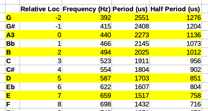
Not sure why but the tones heard differ a little per chip – for example in the recording above they are approximately 3 semitones lower than the expected frequency. Perhaps related to calibration of the microcontroller’s internal oscillator, or some of the “hacks” in the code (see below).
The code
This was written a while ago, added some comments but don’t 100% remember the reasons for some of the hacks:
#include <avr/io.h>
#include <util/delay.h>
#include <avr/sleep.h>
#include <avr/interrupt.h>

#define US_PER_TICK 16000
#define BASE 5

// pre-calculated half-period of each pitch in microseconds
const unsigned short scale[] = {1276, 1136, 1012, 851, 758, 638};

const char encoded[] = {
    // (easy) message part
    6,5,0,2,

    // machine code for the 6502 CPU
    0xa9, 0x74,     // lda #$74
    0x48,           // pha
    0x49, 0x1b,     // eor 0x1b
    0x48,           // pha
    0x29, 0x61,     // and #$61
    0x48,           // pha
    0x09, 0x12,     // ora #18
    0x48,           // pha
    0x69, 0x01,     // adc #$1
    0x48            // pha
};

// hack, _delay_us macro can only take a constant value(?)
// delayed time will be longer than input microseconds
void delay_us(unsigned long us) {
    for (unsigned long c = 0; c < us; c++)
        _delay_us(1);
}


void do_char(unsigned char c) {
    // convert the input byte to digits in the base
    unsigned char base_digits[] = {0,0,0,0,0,0,0,0};
    unsigned numDigits = 0;

    do {
        base_digits[numDigits++] = c % BASE;
        c /= BASE;
    } while (c);

    // for each digit, retrieve the half-period from scale and modulate
    // (toggle carrier pin on-off) using blocking timed delay
    do {
        unsigned half_period = scale[base_digits[--numDigits]]/2;

        // not sure why elapsed is += period/4 and not period here..
        // maybe a hack to slow it down?
        for (unsigned long elapsed = 0; elapsed < US_PER_TICK; elapsed += half_period / 2) {
            DDRB = 0;
            delay_us(half_period);
            DDRB = _BV(PB0);
            delay_us(half_period);
        }
        _delay_ms(50); // delay between digits
    } while(numDigits);
}


void encode_message(void) {
    for (int i = 0; i < sizeof(encoded); i++) {
        do_char(encoded[i]);
        _delay_ms(200); // delay between digit groups
    }
}


int main(void) {
    // internal oscillator tuning/calibration byte
    // enable external interrupts on push button pin to wake from sleep
    OSCCAL = 0x6C;
    GIMSK = _BV(INT0) | _BV(ISC00);

    // setup timer & carrier signal
    // divide clk by 4
    // CTC timer mode, toggle OC0A on compare match
    // timer clock source = CPUclk with no prescaling
    OCR0A = 3;
    TCCR0A = _BV(COM0A0) | _BV(WGM01);
    TCCR0B =  _BV(CS00) ;

    while(1) {
        // before sleep,
        DDRB = 0;
        PORTB = _BV(PB2);           //pullup button
        set_sleep_mode(_BV(SM1));
        sei();                      // enable interrupts
        sleep_mode();
        cli();                      // disable interrupts

        // wakeup
        DDRB = _BV(PB0) | _BV(PB3);
        PORTB = _BV(PB3);           //pull up on LED
        encode_message();
    }

}

ISR(INT0_vect) {}
