Z180 Retrocomputer: Booting
Time to boot it up! A continuation of the Z180 Retrocomputer project. Here, we look at the Z180 MMU behaviour, initialising the system and writing a small bootloader. See also Z180 Retrocomputer: Design for more about the design and construction of the system.
Most of these programs will be written in assembly. While any Z180 assembler would be ok, I’m going to use zasm. The macro/directive syntax might be zasm-specific. The full bootloader code is available on Github.
Memory Management
As the Z180 boots, it will begin executing code from physical address 0x0000 – which is the start of the mapping for the ROM. So we will need to write some code to the ROM that will be run as soon as the device boots.
The Z180 has a 1MB physical address space. In our system, ROM is mapped to the first 512kB (repeated every 32kB), and the RAM is located in the second 512kB. The CPU, however, only has a 64kB logical/virtual address space. This limitation is addressed (pun intended) through common and bank areas. The logical to physical translation can be congfigured to allow for different memory setups:
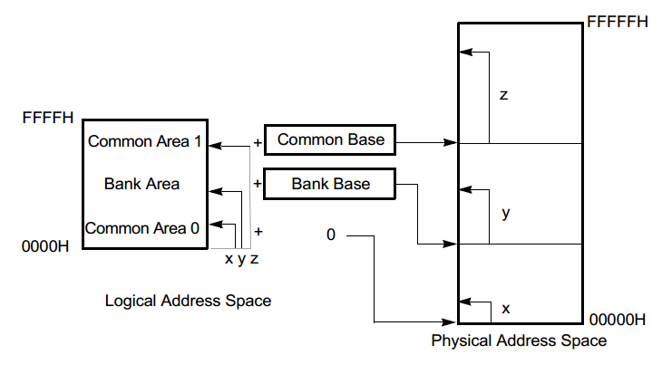

I don’t plan on using the ROM for anything besides this small bootloader. Eventually I would like unmap it, so the whole logical address space can be used as RAM. At this stage the bootloader is being executed from ROM. In stages, we can map the RAM in also, copy the bootloader to RAM, continue executing from RAM, and finally map the ROM out.
| Step | Bank | Virtual Address | Physical Address |
|---|---|---|---|
| Boot | Bank | 0x0000-0xffff | 0x0000-0xffff (32KB ROM, repeated) |
| Initialisation | Common 1 | 0x8000-0xffff | 0x80000-0x87fff (first 32KB RAM) |
| Bank | 0x0000-0x7fff | 0x0000-0x7fff (32KB ROM) | |
| Post-initialisation | Common 1 | 0x8000-0xffff | 0x80000-0x87fff (first 32KB RAM) |
| Bank | 0x0000-0x7fff | 0x0000-0x7fff (first 32KB RAM) |
In both initialisation and post-initialisation, the second configuration in the diagram (bank + common area 1) is used. This gets the CPU into the ‘initialisation’ state:
init_mmu:
  ld a, 10000000b           ; CBR1@0x8000, BANK@0x0000
  out0 (CBAR), a
  ld a, 10000000b - 1000b   ; CBR1 maps to second 512
  out0 (CBR), a
Initialisation
To get the serial port working, the Asynchronous Serial Communication Interface (ASCI) needs to be configured. The USB-serial adaptor is connected to channel 0. In control register CR0A, we enable the transmitter & receiver, and set the mode to 8 bit data, 1 stop bit, 0 parity. In CR0B we set the general divide ratio to be φ ÷ 160. The clock speed is φ = 3.072MHz (half the crystal frequency) so the baudrate becomes 19200.
The stack pointer is initalised to a high part of RAM (stack grows downwards). Some test messages are printed useing subroutines to see if the stack is working. This also tests if RAM is mapped correctly to the stack area.
Leap of Faith
We can use the ldir instruction to copy a chunk of memory containing this bootloader across to RAM:
  ; copy ourselves from ROM -> RAM
  ld bc, 04000h ; count
  ld hl, 00000h ; src
  ld de, 08000h ; dst
  ldir
In the initialisation and post-initialisation mappings, the logical addresses of the programs should be the same, despite the programs being stored physically in separate places. If we change the base of the bank section to the start of RAM, the program should ‘leap’ and execute any further instructions from RAM instead of ROM.
                        ; leap of faith, currently executing from ROM
  ld a, 10000000b       ; bank starts at second half of physical memory
  out0 (BBR), a         ; write it to the bank base register
                        ; anything hereafter is executed from RAM!
Bootloader
Running from ROM is a bit cumbersome, due to the need to physically replace and reprogram the IC with each update. This makes it pretty hard to debug too. Instead, we will write a small bootloader that loads a program via the serial port into memory that we can execute.
Intel HEX
A simple format for representing binary data is the Intel hex format. It is widely used for programming microcontrollers and ROM memory, for example. What makes it particularly useful also is the data is just a stream of ASCII characters with a simple structure – allowing it to be easily parsed and transferred via a serial link. zasm can produce its output directly in Intel Hex format.
A file consists of multiple lines of text, each line corresponding to a record:
Structure :data byte countaddressrecord typedatachecksum\n
Example :16100000210710CD3B01C9546869732069732061207465737421BA\n
A record type of 00 indicates data, and 01 indicates end of tile as the final record. While there are others also, we will implement this subset.
Implementation
As it’s a simple format, it’s not difficult to parse. The helper subroutines have been omitted here:
read_record:
  call in_char          ; get a char
  cp ':'                ; it should be a ':'
  jr nz, .error_reading ; otherwise it's an error
  call in_byte          ; read the byte count
  ld b, a               ; store byte count in b
  call in_short         ; read the start address
  call in_byte          ; read the record type
  cp 1                  ; is it 1?
  jr z, .eof            ; then it's the end of the file
  cp 0                  ; is it NOT 0?
  jr nz, .error_reading ; then it's unsupported / error

.data_record:           ; it is 0, and a data record
  call in_byte          ; get a byte
  ld (hl), a            ; store byte
  inc hl                ; inc out pointer
  djnz .data_record     ; dec remaining bytes, loop while > 0

  call in_byte          ; consume checksum (is unchecked)
  call in_char          ; get new line (assume single \n)
  jr read_record        ; read next record

.error_reading:
  ld hl, err_msg
  call puts
  jp read_intel_hex     ; try again.

.eof:
  call in_byte          ; checksum (is unchecked)
  call in_char          ; get new line (assume single \n)

  ld hl, done_msg
  call puts
Loading Programs
We’ll assume that the test programs we write for now have an entry point at 0x1000. Once the program has finished loading, we can begin execution from there by calling 0x1000. If the program rets nicely, we can try loading and running a new program immediately. This is useful for quickly making and testing new changes.
  call dump_memory      ; dump memory just loaded to debug
  call print_nl
  ld hl, hex_done_msg
  call puts

  call 0x1000           ; call the program just loaded
  jp read_intel_hex
Now we’re ready to load something!

Up Next
In Part 3: We start writing and loading some programs for the system. Coming soon!
Todos
- change the post-initialisation mapping to use the full first 64kB of RAM
- this variant of the Z180 supports clock speeds at the same frequency as the crystal (instead of half). We can write to a control register to enable this.
- the baudrate is wrong in the message (19200 not 38400)
- Intel Hex bootloader: each line is allowed to end with a newline (\n), a carriage return (\r) or both. We only allow a single newline only here. zasm produces hex files with both (even under Linux) – so it fails to load it unless the endings are first convered. So would be helpful to update this sometime.
